Components and systems for terahertz applications
Detector/emitter mounts
Overview
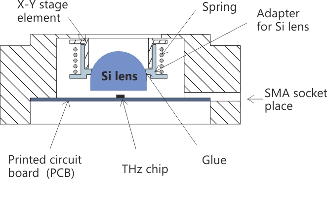
Detector/emitter mount consist of printed circuit board (PCB) used to attach detector/emitter, silicon lens and integrated XY stage for silicon lens adjustments. Technical drawings are shown in Figure 1 and Figure 2. Typical set consist of 1 PCB, 1 silicon lens (see availability of silicon lenses under item "Silicon lenses"), 1 integrated XY stage with micrometric screws for silicon lens adjustments,1 SMA socket.
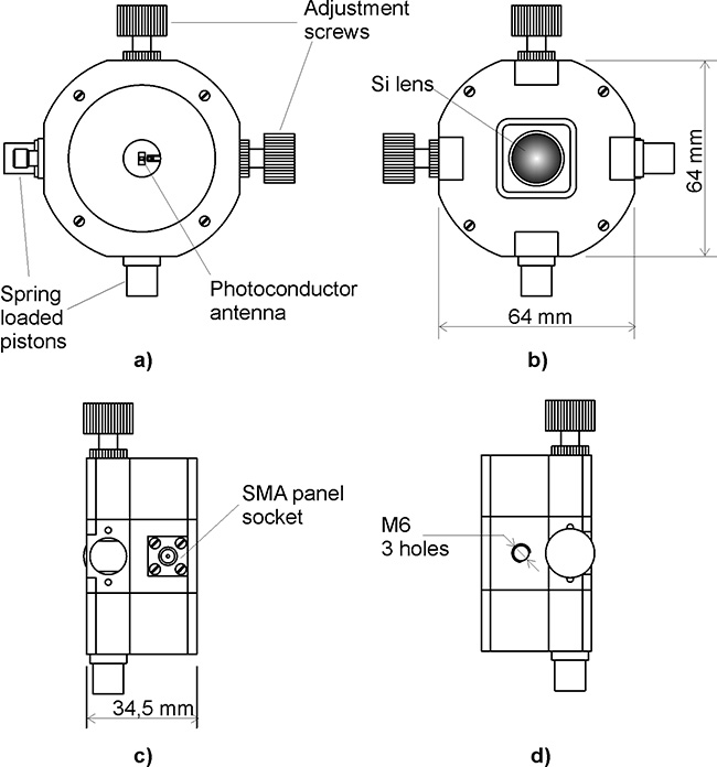
THz emitter (detector) is illuminated by laser beam from panel (Fig. 4-4 a) side. Laser beams must be focused into photoconductor antenna gap. In the case of THz emitter Si lens (Fig. 4-4 b) is used for THz radiation output. In the case of THz detector Si lens is used for THz radiation input. Adjustment screws are used for Si lens positioning in point of view of microstrip antenna center. SMA socket (Fig 4-4 c) is used for connecting DC bias voltage source to the antenna (THz emitter case) or while connecting lock-in amplifier input with THz detector. Any of three M6 holes (Fig. 4-4 d) can be used for THz emitter (detector) mounting on optical table.