Free space Terahertz Emitter
 |
Download datasheet |
Features
- Based on LT-GaAs or GaBiAs photoconductive material
- Optimized for wavelengths around 800 nm or 1060 nm
- Wide spectral range and low noise
- Sub-picosecond temporal resolution
- Technical passport and test report included
Applications
- Time-resolved broadband THz spectroscopy
- Optical pump - THz probe spectroscopy
- THz imaging
Principle of Operation
THz emitter consists of a microstrip photoconductive antenna (PCA) fabricated on GaAs substrate. Depending on pump laser wavelength either low temperature grown GaAs (LT-GaAs) or GaBiAs is used as photoconductor. On its surface a coplanar Hertzian type dipole antenna structure is formed using AuGeNi metallization. Photoconductive antenna geometry, as well as the properties of photoconductor epitaxial layers are optimized for highest THz radiation output efficiency, while preserving optimal bandwidth. As a result, typical emitted THz radiation power exceeds 10 µW, when pumped by laser with 30 mW output power and <150 fs pulse duration.
THz emitter is illuminated by laser beam from panel side. Laser beams must be focused between two electrodes (Fig. 1). The gap between metallic contacts is larger than the laser spot. THz radiation is collected by integrated lens, manufactured from high-resistivity silicon (HRFZ-Si), mounted on X-Y stage (Fig. 2). TERAVIL offers two standard types of these lenses: for collimated or diverging THz beam output. In second case PCA is placed in aplanatic point of silicon lens, which reduces THz beam spherical aberrations. Adjustment screws are used for Si lens positioning onto PCA center. SMA sockets on back side of the housing are used for connecting DC or AC bias to THz emitter. Any of three M6 holes can be used for THz emitter mounting on optical table (Fig.3).
 Fig 1. Microstrip antenna drawing |
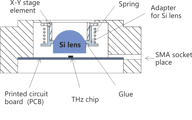 Fig 2. THz emitter crossection |

Fig 3. THz emitter/detector housing
Specifications
|
|||||||||||||||||||||||||||||||||||||||||||||||||||||||||||||
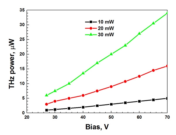 Fig 4. EMT-8 (LT-GaAs) THz emitter radiated power* dependance on bias voltage and laser excitation power |
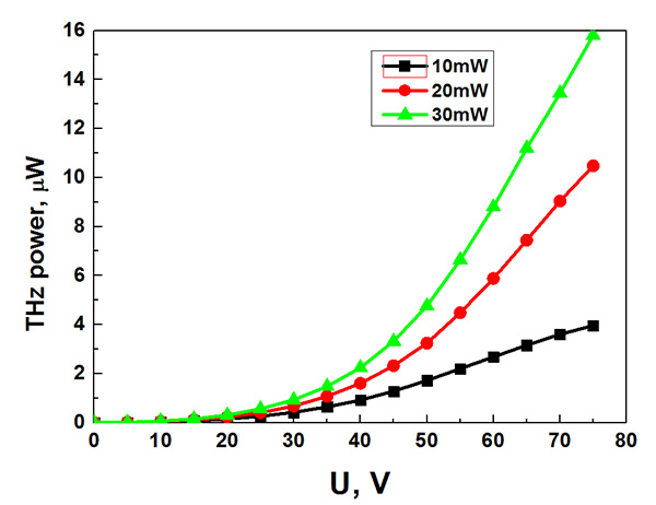 Fig 5. EMT-10 (GaBiAs) THz emitter radiated power* dependance on bias voltage and laser excitation power |
*Measured using TYDEX Optoacustic detector GC-1P (Gollay Cell).

Fig 6. THz emitter mounted on standard optics holder
Ordering Information
|